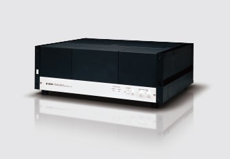
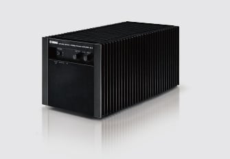
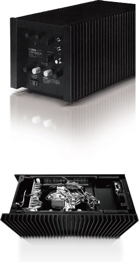
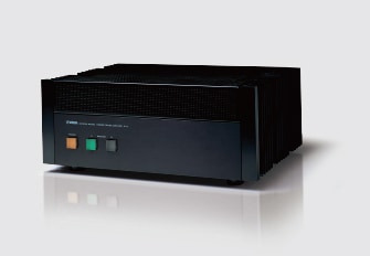
Around the time in 1970 when Yamaha decided to enter the component stereo market, the device of choice for audio output had just changed from vacuum tubes to semiconductors, but audio lovers were vocally dissatisfied with transistor amplifier sound quality. In order to enter the market for high-end audio, Yamaha electronic engineers looked for a device with the sound quality of vacuum tubes and the efficiency and reliability of semiconductors, and their eyes fell upon a new type of semiconductor device, the SIT (static induction transistor). The SIT had just been announced by Junichi Nishizawa, at that time a professor at Tohoku University, who was an authoritative figure in the semiconductor technology world and who had been advising Yamaha on developing semiconductor technology. The SIT had many advantages such as faithful low-distortion amplification of the input signal, high-speed operation and low power consumption. As such it was a truly ideal amplifier device, potentially able to combine the electrical characteristics of vacuum tubes and the efficiency of semiconductors. With the cooperation of Professor Nishizawa, Yamaha was able to bring the SIT into actual production in only a year and a half, a feat that had been considered impossible in the industry, and used it in the first Yamaha stereo power amplifier, the B-1. There were a total of six types of Yamaha FETs used in the B-1, three vertical and three horizontal, and a total of 14 FETs used in each channel. All stages were direct coupled and used Yamaha FETs. This plus a three-step amplifier and a source follower with single-polarity (N type) output devices in a semi-complementary single push-pull resulted in an ideal configuration and made for a beautiful circuit diagram. The 2SK77 output vertical power FETs in their single push-pull configuration achieved an actual power output of 150W + 150W and had wonderful potential. The origin of the Yamaha HiFi amplifier design concept of choosing ingredients carefully and using a simple recipe can be seen in this model. The chassis layout was divided into thirds, with separate power transformers on the left and right, block aluminum electrolytic capacitors (a total of 60,000μF) in the center for each side, and the amplifier circuitry was also completely separated into left and right. Without using words the B-1 conveyed a feeling of ideal amplifier design and bottomless power, a superb job by the GK design group. The shock of its appearance to the audio world exceeded even that given by the CA-1000 integrated amp the year before, and made Yamaha much more visible in the audio world.
History of Separete Amplifier
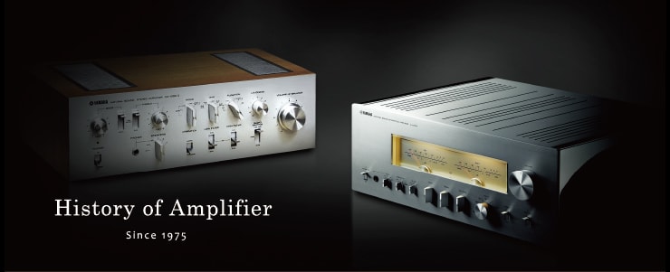
The History of Yamaha Separate Amplifiers (Since 1974)
A mere two years after re-entering the HiFi component market in 1974, Yamaha shocked the audio world again with the first all-FET power amplifier, the B-1, which used a vertical power FET (SIT) developed in house. The next year, the C-1 dreadnought-scale control amp far surpassed conventional models, and in 1976 the slim C-2 followed quickly in succession, winning worldwide praise. Many of the technical innovations were used in integrated and AV amplifiers later, and formed the base of Yamaha’s sound creation.
1974
The dream output element, the vertical power FET, was used for the first time in this all-FET power amplifier.
B-1
open
close
1975
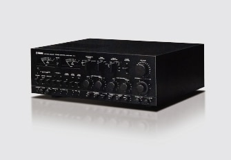
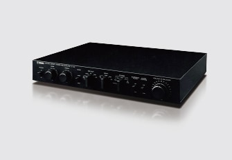
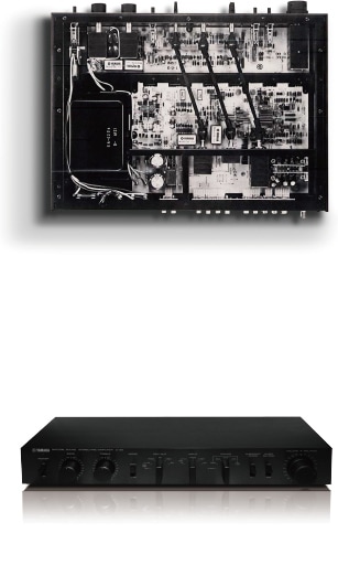
An All-FET high-end control amplifier that combined musical concepts with advanced sound quality control features.
C-1
open
The C-1 was a separate stereo control amplifier using all-FET circuitry in all audio stages. Its rich selection of input terminals included three phono inputs and level controls on each input. Advanced features such as peak level meters and oscillators for checking the complete audio system, and in particular the settings Acoustic (70Hz/300Hz) intended for bass compensation and the parametric equalizer with Presence (2kHz/4kHz) for adjusting the musical balance of the vocals, the precision resistance bass/treble switching (turnover frequency selectable), and the continuous loudness control that adjusted the sound field to human sensibilities, combined to provide complete tone control functionality and demonstrate this model’s concept of musicality. The circuit configuration emphasized high signal-to-noise ratio, and dynamically chose between high amplification and low amplification FET amplifiers as needed. The phono equalizer was two unit amplifiers in series, sandwiching a CR-type equalizer, a configuration that eliminated overall negative feedback, and the first unit amplifier stage operating on +100V/-110V power, allowing it to accept a wider range of input levels, which was a luxurious, creative configuration that attracted the eye. The C-1 was truly a dreadnought class product, and was intended to be released at the same time as the B-1, but it had such far-ranging design requirements that it ended up being delayed by a year. When it was released, using it together with the B-1 made it possible to use FETs for the entire amplification chain, a first for the audio world.
close
1977
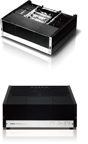
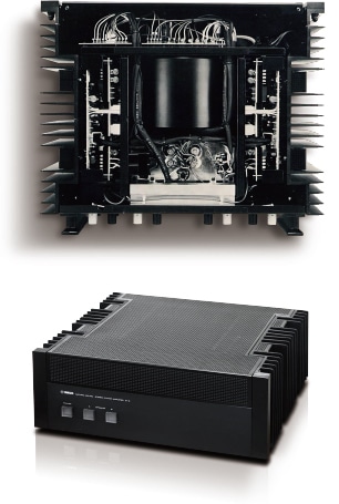
Yamaha’s final SIT amplifier, fully realizing the capabilities of complementary SIT technology.
B-3
open
The B-3 was the third SIT power amplifier, following on the heels of the B-1 (1974) and the B-2 (1976), and was the last of Yamaha’s SIT power amplifiers. The power output device was the 2SK76A/2SJ26A, an improved version of the 2SK76/2SJ26 that was developed for the B-2, and was smaller than the 2SK77 used by the B-1 but had the capability of being used as a complementary pair. The audio circuitry followed the latest trend of DC amplification, with the first stage being a cascode bootstrap differential amplifier using a Yamaha original 2SK100 low-noise dual FET, the pre-drive stage a transistor current-mirror differential amplifier, and for the drive stage, in order to realize the full benefits of the pure-complementary SIT output stage, a pure-complementary symmetrical push-pull drive using a push-pull circuit with both n-channel and p-channel FETs was designed and used. For the power supply, Yamaha original low-multiplier etched aluminum electrolytic capacitors (27,000μF) as well as a Mylar capacitor (10μF) were developed especially for this model, and these combined with the 2.5mm copper ground plane to reduce impedance over the whole frequency range. The erect cubical design had different proportions from other Yamaha power amplifiers, and this design decision was probably due to the use of a bridge-tied load configuration that allowed both channels of the output stage to be used together with BTL for monaural operation. At that time the audio world’s belief in high power was much stronger than today, and especially overseas the B-3 was not appealing due to its having only 70W + 70W power, comparable to an integrated amplifier. As stated above, this model became Yamaha’s last SIT model, and in Yamaha’s pursuit of the ultimate device the SIT production yield was low, making it expensive. Also, the fact that the demand for it in applications other than power amplifier output stages was low, its insufficient power and distortion ratings compared with transistors of the same price range, and the appearance of new amplifier technologies such as DC amplification and high-efficiency class A all combined to make the SIT impractical. In the following models, Yamaha focused on developing low crossover distortion technology using conventional transistors or MOS-FETs, and achieved sound quality surpassing the SIT with such innovations as the Linear Transfer Circuit (1979), the Dual Amp Class A Circuit (1983), the HCA Circuit (1987), and the present-day Floating and Balanced Circuit. But the philosophy and creativity behind the SIT development is still around today.
close
1978
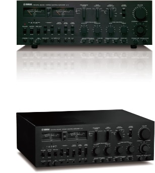
The appearance didn’t change, but the inside was all new on this reference control amplifier.
C-2a
open
The C-2 (1976) was the first shot fired in the domestic thin-style control amplifier war, and the C-2a was an improved model released two years later in 1978. Only someone especially interested in the series would notice the differences between these two, as there is not so much difference either in appearance or features. But if you took off the bottom cover (the C-2 series cabinets had a one-piece front/top cover made of extruded aluminum, and the circuit boards were hung upside-down from the top), you would see that the only common components were a few lever switches, and that the circuit configuration and chassis layout had been completely redesigned. If you look at the catalog the first big difference is the distortion and signal-to-noise ratio specifications. Actually there was no difference between the two when measured in a conventional way, but this was because the C-2a’s distortion was lower than the residual distortion of the test equipment, so for the development of this model it was necessary to start using a computer-controlled audio analyzer capable of analyzing harmonic distortion to a 0.00005% order, and with this equipment the total harmonic distortion measured from the phono (MM) input to the Record Out terminals (20Hz — 20Khz, total from second to tenth order) and shown in the specifications was an astonishing 0.0007%. The audio circuit used an all-DC configuration, and instead of the 2SK100 super-low-noise dual FET used previously, it featured the new 2SK101 low-noise, high-transconductance dual FET in the first stage. In place of the old C-2’s low-noise integrated head amplifier, it was notable that a fully discrete DC configuration with ten low-noise transistors in a cascode complementary push-pull was used. In all, the C-2 used 61 bipolar transistors, six FETs, and two integrated circuits, but the C-2a used 101 bipolar transistors and five FETs. When the C-2a was released the price was 170,000 yen, 20,000 yen more than the C-2, but was actually low considering its high efficiency. Where you might have expected streamlining you actually saw more than before, and you sensed the passion of the developers. The C-2a was highly rated even overseas, and was on sale for five years as a reference-model control amplifier, until it passed the baton to the again-renewed C-2x in 1983.
close
1979
Linearity at low sound levels, and high power output: you got both with the Linear Transfer Circuit.
B-5
open
The B-5 was released in 1979 as a successor to the B-3, the last of Yamaha’s SIT amplifiers, and it was developed with the goal of surpassing the charming sound quality of the SIT without using SITs. In order to accomplish this, it was necessary to use the advanced circuit design of the Linear Transfer Circuit to cover the conventional bipolar transistors’ weakness with respect to crossover distortion compared to the SIT. The principle of the Linear Transfer Circuit was that three groups of power transistors in a triple push-pull had staggered operating points with different bias current settings, and their combination was nearly a second-power characteristic, so that the linearity and distortion specifications at low signal levels, which tended to be poor with high-power amplifiers, were improved. The output devices were Yamaha-developed original 2SC2707/2SA1147 high-transition-frequency (broadband, high-speed) transistors with copper cases and copper screws to reduce current distortion, which achieved 240W + 240W (8 ohms, 20Hz — 20kHz, 0.005% THD) high power and low distortion, at levels that had not been attained with the SIT. Of course, the B-3 BTL (bridge-tied load) switch was eliminated. The huge power supply section used a giant toroidal transformer filling a full one-fourth of the volume of the chassis, professional-audio low-multiplier block aluminum electrolytic capacitors with the world’s first non-magnetic polypropylene case, and the heat sinks on both sides were an integral part of the structure enabling a streamlined chassis-less design, keeping the size down to 435×361.5×182.7mm, which was that of a typical economy-priced A/V amplifier, and the weight down to 20.9kg. The upper half of the front panel and the top panel were formed from a single sheet of perforated metal, allowing the interior to be seen, and although the technology was that of the most modern high-power amplifier, the appearance was that of a vacuum-tube amplifier.
close
1980
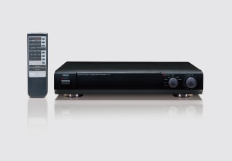
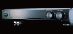
A remote-controlled thin-style control amplifier that aimed to set new standards.
CX-1
open
In the 1990s, video discs and 5.1-channel surround became prevalent and home theater became popular, so the demand for audio amplifiers largely shifted from HiFi amplifiers to A/V amplifiers. Each company retrenched its HiFi lineup, and in particular flagship and high-end model separate amplifiers disappeared. In those years, Yamaha used its accumulated audio technology to provide more reasonable prices, and the new models intended to set new standards for separate amplifiers were the combination of the CX-1 control amplifier and the BX-1 power amplifier. The style set in the era of the C-2 of thin control amplifiers with pure signal paths was unchanged, and if you closed the sealing panel, a simple look with only a volume control, input selector and power switch was revealed. The main difference from the C-2 era was the remote control, and to avoid sound degradation from that, not only the volume control but also the input selector were motor driven. The linkage from the remote control that caused the input selector on the panel to click to the next setting in response was a hidden charm point. Of course the audio circuits were full discrete, and a four-gang volume control that improved the low-volume signal-to-noise ratio and a phono equalizer with an MC head amplifier were quite traditional, but the ART design featuring a high-density anti-vibration base made of special plastic embedded with glass fibers was something that was developed later, and the idea of attaching all components to such a base was a feature that had not been seen before. The CX-1 attained a persistent popularity as a high cost-performance pure audio control amplifier and remained on sale for twelve years until 2005.
close
1993
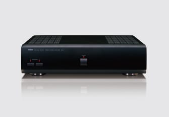
This thin-style high-power amplifier with versatile charm featured the definitive high-efficiency class A amplifier, the HCA circuit.
MX-1
open
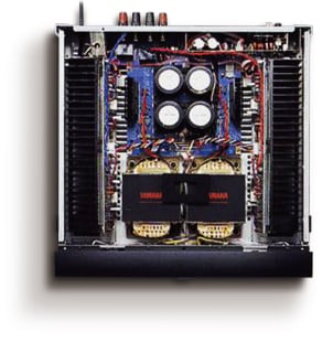
The MX-1 power amplifier went on sale in 1994 along with the CX-1 control amplifier, and though customer interest had moved to audio/visual and the demand for high-end HiFi amplifiers had diminished, this model was intended to harness Yamaha’s accumulated audio technology to provide the most reasonable prices. The power amp section used the HCA (Hyperbolic Conversion class A) operation of Yamaha’s 100-year anniversary Monumental Products 10000 Series, and delivered 200W + 200W (8 ohms, 20Hz — 20kHz, 0.008% THD) rated output and dynamic power capable of driving a low-impedance 2-ohm load at 630W + 630W using a unique linear damping circuit to achieve a damping factor of 350. Inside the slim 116mm high cabinet was a symmetrical layout with huge individual left and right EI power transformers and two 36,000μF block aluminum electrolytic capacitors in the center, so a cabinet depth of 486mm was needed to handle the power block with its large heat sinks. The chassis was a type used even now for both high-end audio and A/V with a double bottom structure, and while it didn’t look it, it was a weighty 24kg, giving it the heft of a pro-class model. This model could have its main power controlled in tandem by the remote control of the CX-1 or other control amplifiers or A/V amplifiers with remote control outputs, and in addition to other uses there was a demand for it for upgrading home theater systems. Like the CX-1, the MX-1 was on sale for twelve years until 2005.
close